
VSA-090-06-6-UE-S
6-Channel Programmable RF Attenuator
Starting price
USD 3,490
Excluding VAT and shipping. Final price, scope and lead time are confirmed in a written quotation. Request a quote
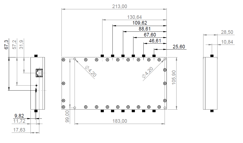
Programmable RF attenuation for six independent channels over 50 MHz to 6 GHz. USB and Ethernet control support fixed-level and attenuation-profile applications.
- 6 independent channels
- 0-90 dB attenuation
- 0.5 dB step
Revision 2026-11-R1 · EN
Technical values refer to the identified source configuration. The applicable configuration and operating conditions are confirmed at quotation.
| Parameter | Condition | Value | Min. | Typ. | Max. | Unit |
|---|---|---|---|---|---|---|
| Frequency range | — | 50 | — | 6000 | MHz | |
| Impedance | — | — | 50 | — | Ω | |
| Attenuation range | — | 0 | — | 90 | dB | |
| Attenuation step | — | — | 0.5 | — | dB | |
| Attenuation accuracy | 0.5-20 dB | — | — | ±0.25 | ±0.75 | dB |
| Attenuation accuracy | 20-40 dB | — | — | ±0.5 | ±1 | dB |
| Attenuation accuracy | 40-63 dB | — | — | ±0.6 | ±1.25 | dB |
| Attenuation accuracy | >63 dB | — | — | ±0.8 | ±1.5 | dB |
| Insertion loss | <2.5 GHz | — | — | 7 | 7.5 | dB |
| Insertion loss | <5 GHz | — | — | 10 | 10.5 | dB |
| Insertion loss | <6 GHz | — | — | 11 | 11.5 | dB |
| VSWR | — | — | 1.5:1 | 2:1 | ||
| Input-output isolation | — | 95 | 100 | — | dB | |
| Channel-to-channel isolation | — | 70 | 75 | — | dB | |
| RF input power | — | — | — | +26 | dBm | |
| Input IP3 | — | 50 | 55 | — | dBm | |
| Independent channels | 6 | — | — | — | ||
| Control | USB / Ethernet | — | — | — | ||
| Power supply | 5 V DC (USB) | — | — | — | ||
| RF connector | SMA (f) | — | — | — | ||
| Source body dimensions | 213 x 105.9 x 28.5 | — | — | — | mm | |
| Mass | 520 | — | — | — | g |
Applications
- Controlled RF path-loss tests
- Multi-channel MIMO setups
- Automated test sequences
Changing attenuation on one channel at 1 GHz
Each RF path has its own input and output. Each of the six channels can be set independently from 0 to 90 dB in 0.5 dB steps.
Use USB or Ethernet for control. The unit receives power over USB.
| Channel | A (dB) | B (dB) | B − A (dB) |
|---|---|---|---|
| 1 | 10 | 10 | 0 |
| 2 | 10 | 10 | 0 |
| 3 | 10 | 30 | +20 |
| 4 | 10 | 10 | 0 |
| 5 | 10 | 10 | 0 |
| 6 | 10 | 10 | 0 |
Test sequence
- At 1 GHz, keep the input level, cables and measurement reference fixed. For setting A, set all six channels to 10 dB and measure the outputs of the channels you want to compare.
- For setting B, change only channel 3 to 30 dB. Repeat the measurements and compare each channel with its own reading from setting A.
The +20 dB on channel 3 is the difference between programmed attenuation settings. Account for insertion loss and attenuation accuracy when interpreting measured path loss. Technical specifications.
VSA-090-06-6-UE-S